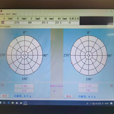
Product Details:
|
Max Mass Of Workpiece: | 1kg,5kg, Optional | Max Diameter Of Workpiece: | Ø 150 |
---|---|---|---|
Distance Between Two Support Bearings: | Minimum 100, Maximum Blade Length 1200 | Support Shaft Diameter Range: | Ø 5~Ø 40 |
Balance Speed: | Frequency Conversion Stepless Speed Regulation | Motor Power: | 0.25 KW |
The Smallest Achievable Residual Unbalance: | URR≥95% | ||
High Light: | Antiwear Fan Balancing Machine,Multifunctional Fan Balancing Machine,0.25KW Cross Flow Fan Balancing Machine |
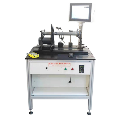
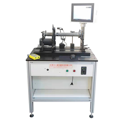
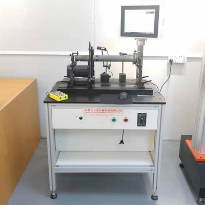
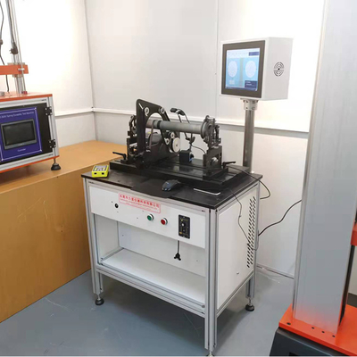
Dynamatic Balance Machine-Cross-Flow Fan Vane Balancing Machine for Air Conditioner Cross-Flow Fan
Overview
The balancing machine is an instrument used to determine the unbalance of the rotor. The balancing machine is a hard-supported balancing machine. The swing frame is very rigid. The measurement result of the dynamic balancing machine is used to correct the unbalance of the rotor, so that the vibration generated when the rotor rotates or acts on The vibration on the bearing is reduced to the allowable range to achieve the purpose of reducing vibration, improving performance and improving product quality.
Cross-flow fan balancing machine is mainly used for the balance correction of the cross flow fan of the air conditioner and other similar rotating parts.
Application
It is mainly composed of high-precision mechanical parts and advanced electrical parts, combined into one hard-bearing balancing machine. This series of products is a special balancing machine developed, designed and manufactured by our company based on the core technology at home and abroad. Mainly used in various rotating workpieces, such as: air-conditioning cross-flow fan blades, automobile air-conditioning heaters, clothes dryers, air curtain machine cross-flow fan blades, etc. balance detection and correction.
This electromechanical measurement system can be equipped with a microcomputer digital display test, or it can be equipped with a computer measurement, which can be configured according to the actual needs of the user.
Technical Parameters
Model | HZ-9709A-1 | HZ-9709A-5 |
Max Mass of Workpiece(kg) | 1 | 5 |
Max diameter of Workpiece(mm) | Ø 150 | Ø 150 |
Distance Between Two Support Bearings (mm) | Minimum 100, maximum blade length 1200 | |
Support shaft diameter range(mm) | Ø 5~Ø 40 | Ø 5~Ø 40 |
Balance speed (r/min) | Frequency conversion stepless speed regulation | |
Motor Power (kw) | 0.25 | |
The smallest achievable residual unbalance (g.mm/min) | emar≤2 | |
The smallest achievable residual unbalance (g.mm/min) | URR≥95% | |
Measuring system | Microcomputer digital electrical measurement system (optional computer measurement system) | |
Note: The technical parameters of the above series of balancing machines are for reference only. The specific parameters and quotations need to be determined according to the actual situation of the rotor of the user's workpiece, and can also be customized. |
Influence of balance machine
1. The left and right support points are high and low, which makes the rotor move left and right or the journal plane rubs against the support point.
2. The support block is severely worn or the roller jumper increases.
3. There is dirt on the support and no lubricating oil is added.
4. The foundation on which the balancer is installed does not meet the requirements, the bottom joint surface is not padded, the anchor bolts are not tightened, or it is placed on the floor, causing resonance.
5. The output signal of the sensor is abnormal.
6. The fastening screws at the movable parts on the support frame are not tightened.
7. The transmission belt does not meet the requirements and has obvious seams.
8. The photoelectric head of the balancing machine is not aligned with the front and reflective paper, the mirror of the photoelectric head is blurred, and the position of the photoelectric head is skewed to cause an angle shift.
Purpose
An unbalanced rotor generates a pressure on its supporting structure and the rotor itself during its rotation, and causes vibration. Therefore, the dynamic balance of the rotor is very necessary. The balancing machine is to check the dynamic balance of the rotor in the rotating state. The function of dynamic balance is:
● Improve the quality of the rotor and its components
● Reduce noise
● Reduce vibration
● Improve the trial life of supporting parts (bearings)
● Reduce user discomfort
● Reduce the power consumption of the product
Unbalance amount calculation
Where mper is the allowable unbalance:
M: represents the weight of the rotor, the unit is kg
G: represents the balance accuracy grade of the rotor, the unit is mm/s
r : represents the correction radius of the rotor, the unit is mm
n: represents the speed of the rotor, the unit is rpm.
Annex
The balanced quality grades of commonly used various rigid vermilion drills
Balance quality grade | Eper.ω mm/s | Type of rotor |
G 0.4 | 0.4 | Spindle, grinding wheel, motor rotor and gyroscope of precision grinder |
G 1 | 1 |
Tape recorder and record player, CD, DVD drive, grinding machine spindle drive and electric cabinet, small armature for special requirements
|
G 2.5 | 2.5 |
Gas and steam turbines, machine tool drives, special requirements of medium and large motor rotors, computer storage drums or disks, turbine compressor rotors, small armatures that do not meet one of the two conditions of G6.3, turbo-driven pumps
|
G 6.3 | 6.3 |
Paper machine drums, printing press drums, main turbine gears of merchant ships and marine vessels, high-speed separator drums, fans, fans, blowers, rotor parts of aviation gas turbines, flywheels, pump impellers, machine tools and general machinery, generally medium-sized And large motor rotor (shaft center height of more than 80mm) mass-produced small armatures whose installation conditions are not sensitive to vibrations. Vibration isolation devices are provided, and individual parts of the engine with special requirements. Supercharger rotors.
|
G 16 | 16 |
Drive shafts with special requirements (propeller shafts, universal joint drive shafts), parts of grinders, parts of agricultural machinery, individual parts of automobile engines, crankshaft drive parts of six-cylinder and multi-cylinder engines with special requirements, metallurgy, chemical industry, Parts of continuous process machinery in petroleum and other refineries, main turbine gears of ships (merchant ships), centrifugal separator drums
|
G 40 | 40 |
Automobile wheels, hubs, rims, wheel assemblies, drive shafts, elastically installed six-cylinder or more high-speed four-stroke (gasoline or diesel) engine crankshaft drive devices, and engine crankshaft drive devices for automobiles, trucks and locomotives.
|
G 100 | 100 |
Crankshaft drive device of six-cylinder or more high-speed diesel engine, complete engine (gasoline or diesel) of automobile, truck and locomotive
|
G 250 | 250 |
Rigidly mounted high-speed four-cylinder diesel engine crankshaft drive device
|
G 630 | 630 |
Rigidly installed crankshaft drive device of large four-stroke engine, elastically installed crankshaft drive device of marine diesel engine
|
G 1600 | 1600 |
Rigidly mounted crankshaft drive device of large two-stroke engine
|
G 4000 | 4000 |
Crankshaft drive device of low-speed marine diesel engine with odd number of cylinders rigidly installed
|
Contact Person: liang
Tel: 8613711888650
Fax: 86--13827265866